
Via DIY
Via began as a DIY project, and Starling wouldn't exist without synth DIY. We think that it can expand accessibility to hardware synthesis tools, foster a deeper relationship between artist and instrument, and inspire technical innovation.
Distributing Via as a DIY project presented an interesting choice. On one hand, we have done our fair share of SMT builds, and we know all about the strange satisfaction and cost-savings of being a human pick-n-place. On the other hand, having built many prototypes by hand, we know how difficult and time-consuming the process can be (certainly not something for inexperienced builders).
For our initial run, we have chosen to distribute pre-SMT populated boards, making the project accessible to beginners and quick work for more experienced builders. It also gives us a better shot at covering development and production costs on a project years in the making. In the spirit of DIY, we have made the schematics and source code available for anyone who wants to dive deep into the design and use some or all of it for derivative works or other projects.
Now that you know a bit more about where we are coming from, the following resources will take you from pre-populated circuit boards to a fully functional module.
You can get your kit at Modular Addict.
1. Build Guide
Break down your panel
Admire the panel one last time then break it along the scored lines with your hands. Snap off the tooling rails with some pliers. To save yourself from splinters, use the edge of the blank panel to buff the scored edges. Mind your fingers while you do this.
Make and place 17-pin headers.
Snap off two sections of the .1" single row header pins so you have 17 pins on each. Cut down a pair of 17-pin socket headers to match. Push the long end of the pins into the socket headers.
Seat the headers in the analog and digital board. It will make your life easier to solder the socket headers into the smaller digital board and the pin headers into the larger analog board.
Note that the SMT parts are facing up on both boards when you make the header sandwich. Take care when placing the headers unless you want desoldering practice.
Stack the two boards and solder the headers.
Take your time with this part to ensure proper alignment. Add light pressure so that the headers are flush with the PCB as you begin to solder. Solder the pins on the two opposite corners of the digital board and check that the headers are still aligned correctly.Once you are satisfied with the alignment, secure the headers by soldering the rest of the pins, then flip and repeat with the other side. You can now separate the two boards.
Add the digital board power header.
Snap off a 10-pin chunk of the dual-row .1" headers, place it so the pins are sticking up from the component side of the board, and solder it in place, tacking a single pin down first to lock in alignment. It helps to prop up one side of the board to make sure that the header lies flush with the PCB.
This revision can only accommodate an un-shrouded header, but red stripe is down, and the power circuit is reverse protected.
Add the digital board expander header.
As you can tell from the false start in the video, getting the alignment is a bit tricky, but you can prop up the digital board with the other boards to make it easier to get the first solder joint in place.
Attach the expander header.
Let's get the headers out of the way. Break away a 12-pin chunk of .1" dual-row pin headers and place it on the silkscreen indicator (the pins stick up from the component side of the board). Solder from the opposite side as shown.
As with all the other headers, figure out a way to get the alignment, tack a corner, and secure all the pins once your first solder joint locks in the alignment.
Phew, headers are done!
Insert the pots into the analog board.
Insert the pots into the side of the board with the silkscreen outlines. Note the placement of the 50K pot. When placing the pots, it helps to lead with the 3 pins and then push the lugs through.
Place the LEDs.
You might want to start with the cloudy bicolor LED so you don't mix it up with one of the clear white LEDs. For all 5 of the two-legged LEDs, in this corner of the universe the short lead goes to the square hole. You can let the LEDs sit in the holes against the PCB for now.For the RGB LED, the longest lead goes next to the square hole. You might need to fiddle with this one a bit because the holes are close together, which gives you extra time to make sure that you have it oriented correctly.
Place the jacks.
The next step requires attaching the faceplate, so make sure that the faceplate and pot nuts are within reach before you start. Place the jacks while holding the board level with the other hand. The ground pins that stick out from the jacks are all facing up towards the pots.
Attach the faceplate.
Make sure all the pots are sitting flush and then ease the faceplate onto them. It should slide right down and onto the jacks with minimal fiddling. Once it is sitting flush on the pots and jacks, drop one or all of the pot washer/nuts on and secure them enough to hold the board in place.This should make the assembly secure enough to set aside while you prepare to attach the expander.
Place the expander parts.
First off, make sure that you are placing the parts on the side of the board opposite the components (just like the analog board).
Make sure the middle potentiometer is 50k as per the silkscreen.
The jacks have the same orientation as the analog board; ground lug towards the top of the board.
Take care with the orientation of the pushbutton; as shown on the silkscreen, the flatted side goes towards the bottom edge of the PCB.
Attach the expander to the faceplate
Add the rest of the nuts and washers
Now that the full assembly is secure, you can add the rest of the nuts and washers and tighten them up (no need to go overboard with the torque, that can pull the PCBs out of alignment).
A nut driver or socket is recommended, as pliers could mar your faceplate. Finger tightening might be a bit fidgety, but you should be able to get everything tight enough if you have to go that route.
Solder the delicate bits
Make sure the the PCBs are aligned and sitting flush against the components. Tightening the nuts can pull the expander board out of alignment.
The pushbutton needs to be pressed up flush against the PCB when its soldered, so maybe start with that. You can use finesse and hold it up with your solder-feeding hand, or you can make your life easier and prop it up with something. Again, tack a pin and check alignment then secure the rest when you are happy.
The two-legged LEDs should be pushed through the holes in the faceplate as far as possible. The RGB LED gets pulled up so it is flush with the PCB.
TAKE YOUR TIME WITH THE RGB LED, IT'S THE HARDEST PART OF THE WHOLE THING. The hack here is to solder one pin, clip down the leads, then solder the rest to avoid bridges. That makes it comparable to soldering an IC. Go easy on the solder!
Solder everything else
Now you can enjoy the zen of synth DIY and solder all of the remaining connections.
Reattach the analog board to the faceplate and insert the long header.
Insert the long 8 pin header through the analog board so that it is resting lightly in the socket header on the front panel. Attach the digital board to the analog board, seating the long pin headers before fully inserting. Keeping the base of the long pin header flush with the digital board, solder the two opposite pins on the header. Double check the alignment, then solder the rest. When disassembled, the long header stays attached to the digital board.
No Expander?
If you're not using the expander, make sure you place the 3 jumpers as shown here.
Expander?
Insert your expander cable paying attention to the white stripes present on the board and the white wires on the cable. Your Via will be extremely unhappy and likely suffer damage if you reverse this cable.
You're done with the hardware build!
Now, its time to program the microcontroller and calibrate the unit.
2. Calibration
The in-house production assistant firmware is available so that you can test and calibrate your DIY module.
The first step is to flash it using the Viaflash tool.
Assuming you have successfully loaded the firmware onto your module, this guide walks you through the calibration steps:
a. Testing the LEDs and touch sensors
b. Testing the IO and trimming for v/oct.
c. Measuring CV offsets
d. Measuring and storing the signal output offset
1. Testing the LEDs and touch sensors
-
Connect the module to eurorack power so you can access the back side and maneuver easily. Ensure the -12V rail (red stripe) on the connector is facing downwards. Start with nothing plugged into the jacks.
-
If the expander is present, tap the push button to turn the triangle green.
-
Tap each of the touch sensors; they will successively turn on an LED. After all 6 sensors have been been tested, the LEDs go dark and the module moves on to the next calibration stage.
-
All LEDs on the module should be dark.
-
Turn the black knobs fully clockwise.
-
Patch the main logic output to the main logic input. You should see the two left white LEDs blink. If that is successful, unpatch from the main logic input and patch into the aux logic input, if the expander is present. You should see the two right LEDs blink.
-
Test the aux logic input by unpatching from the main logic output, and patch the aux logic output into the aux logic input to verify that output.
-
Patch either logic input into the CV2 input. The triangle should blink red.
-
Patch into the CV3 input and the triangle will blink blue.
-
Currently, v/oct response is only relevant on the Meta and Sync firmwares, so the next steps are optional if you do not plan to ever use the platform for either of those modules. If you want to skip this step, tap the pushbutton to exit this stage or hold any touch sensor for more than a second.
-
Patch the output into an audio monitor. Turn the A and B knobs. The distance between the A and B manual controls sets the level of the output, and when adjusting, ensure that you can hear a stepped response when adjusting either A or B. This verifies that the sample and hold circuits are operational. With the knobs furthest apart, you should see a mix of green and red on the bicolor LED. The output is a test tone that can aid v/oct trimming.
-
The CV1 input is calibrated for v/Oct by means of a trim pot on the analog board. There is a hole in the top left section of the digital board to allow access to the trim pot below. Finding the right screwdriver can be tricky; ideally a trimmer tool such as those from Vishay or Bourns works well and costs a couple of dollars. Get a feel for adjusting the trimmer. It is somewhat fragile.
-
Find a sequencer and set the steps so the first half is at a low note and the second half is some number of octaves(volts) above the low note. A bigger octave jump will require a more precise trim but it will be more sensitive. Patch the sequencer CV output into the CV1 input on the module. Increase the tempo of the sequencer until the output cycles between the high and low voltages about once a second. You can also manually toggle a reference voltage between two values, with an appropriate span.
-
Each rising edge is measured, and the color of the triangular LED instructs you how to correct the error. If its blue, adjust the trim pot clockwise (when looking at the module right side up from the back), if its red, turn it to the counterclockwise. When the jump is correct, the triangle is green.
-
Once you are satisfied with the CV1 response, if you want to use an alternate firmware taking advantage of the signal output v/oct response, patch the signal output into the CV1 input. Use the same method to trim the signal output (the output trim pot is down near the bottom left corner of the analog board). Knob1 sets the speed of the test LFO, knob 2 sets the number of octaves in the jump, and knob3 sets the lower octave.
-
Once you are satisfied with the trimming, REMOVE ALL PATCH CABLES and press the touch button or hold a touch sensor for more than a second. This advances to the next stage when ADC offsets are calibrated.
-
Immediately upon entering this stage, the CV offsets at ground are measured. When measurement is successful, the triangle becomes green.
-
Patch the signal output into the CV1 output.
-
You can now press the pushbutton or hold a sensor and release after a second to advance to the final stage where the signal output offset is measured.
-
Provided you had the signal output properly patched into the CV1 input, the offset of the signal output was just measured.
-
You can now press the pushbutton or hold and release a touch sensor for more than a second to store the calibration data. The LEDs will go dark when the data is stored.
-
Disconnect the module from eurorack power and flash your firmware of choice with the ViaFlash tool. You must use this tool for uploading firmware if you want to maintain calibration data and presets.
3. Troubleshooting
This is a basic troubleshooting guide to help get your Via up and running. It assumes you have no sophisticated tools like a scope, but in case you aren't successful on your first power-up this might help you get going. If you need additional help, look to the forums.
Of course the best first step, even before plugging in your Via, is to double-check your work -- look for unsoldered connections, cold joints or solder bridges.
-
My synth turns off or behaves strangely.
If you feel a component getting very hot on the board, remove it from power immediately to limit the risk of damage. If you have a current-limiting power supply this is a good use case for it, to safely limit the current until you can find what's causing excessive current consumption.
Check the power cable is plugged into your power supply and module correctly. A silkscreen line on the PCB indicates where the red stripe on the power cable should go. Make certain it is correctly seated on the pins. Using the voltmeter mode of a multimeter, put the black lead on one of the GND pins. With the red lead, measure +12v, -12v, 3.3v and 3.3va. If any of them are not what they should be, you can also test for continuity between each of them and make sure they aren't shorted.
Make sure that D6 and D7 near the power header are soldered in and the correct way around, as indicated by the line in the silkscreen and on the body of the diode.
First, make sure that your expander cable is unplugged (either end), and that you're holding down the DFU button while plugging in the module. Double-check that you're using an appropriate cable, and make sure that if you're on windows the appropriate drivers are installed. Follow the instructions on the Viaflash page. If it still seems like your module is not detecting, check the power as outlined above, except using USB to power. You should see a much lower voltage on +12V, nothing on -12v, and 3.3v/3.3va should be present and correct. If that looks good, chances are something is keeping your microcontroller from starting.
Double-check that the microcontroller is seated correctly on the pads and there are no bridges. If you spot one, you can get rid of it by adding some flux to the pins and using a clean soldering iron (not with heaps of solder still on it) heat up the pins and try to lift away the solder. Surface tension should be able to suck the solder onto the iron tip.
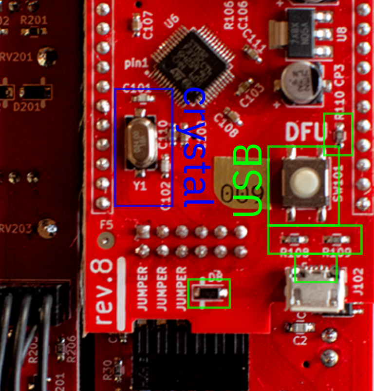
Take a close look at the USB connector and make sure that each of the 5 pins that sit on the PCB are soldered with no shorts. Also look at the diode D8 ensuring that the line on the diode body is oriented to the line on the silkscreen, and check resistors R108, R109, R110 and ensure they are present and soldered correctly.
Make sure the crystal Y1 is oscillating (check the crystal pins with an oscilloscope and see that it is a nice healthy oscillation, and ensure that it's soldered down along with the two crystal capacitors C101 and C102.
First check the soldering on the long 8-pin male header of the digital board. Make sure there are no shorts or cold joints. Check the resistors R101-R106 and capacitors C104-C106 to make sure they're all soldered, and ensure that the microcontroller looks seated properly with no bridges on the pins.
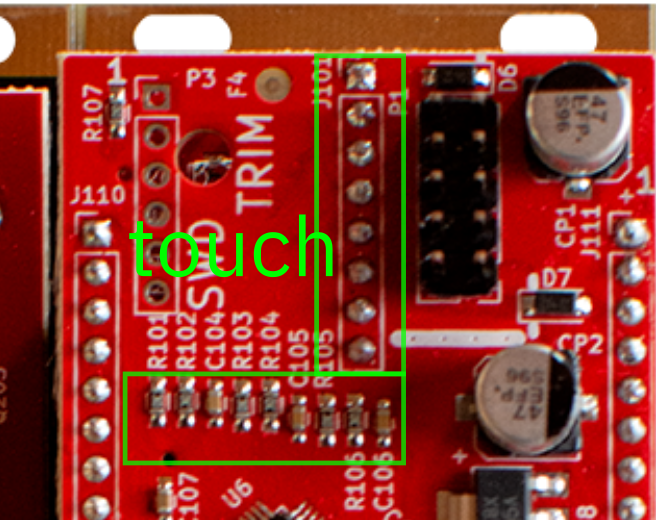
Try touching the pins on the header directly while calibrating to see if you can get it to respond to a touch there. If it does, the problem is likely on the faceplate, and if it doesn't the problem is likely on the digital board.
Check that the SMT header on the front panel is soldered correctly.
If you don't get the RGB to light up, ensure that there are no bridges across the RGB LED pins. This takes some finesse to do right. Remove some solder with solderwick, or add flux to the bridge and try to drag the solder away with a clean soldering iron. Make sure that the LED is oriented correctly.
If the bicolor LED seems to work backwards, desolder it and flip it around.
If the other LEDs fail to light up, check that they're not in backwards.
Check to ensure that the expander cable is plugged in and has the correct orientation. Locate the white stripes on the PCB to the white wires If you aren't using the expander, make sure that the 3 jumpers are placed in their appropriate spots.
If you happened to plug in the expander cable the wrong way, you may damage the manual analog A circuit. You'll know if you don't get a +/-5v swing on the manual A control. If this has happened, the two transistors Q203-Q204 may need replacing. Hot air is the easiest way to get these off of the board without pulling up traces in the process, but it can be done with a soldering iron by heating up an entire side of the package, and bending that side up and away from the pads.
Resistors were chosen to get the trimmer adjustment range sensitive enough to be both accurate and easy to trim. In a few cases the manufacturing error in the resistor values are such that the trimmer doesn't have enough range to bring into tune. If you are turning all the way clockwise( is this right? ) and you run out of room on the trimmer, remove R36 (or R35 for output trim) and replace with a solder blob or short out the pads with a very small piece of wire and solder. If you are turning all the way counterclockwise, you can replace R36 (or R35) with an 0603 1k resistor.
4. Faceplate Swap
Once you have your module built (or if you bought a preassembled module) you may want to swap the faceplate to transform your Via into one of its family members. The following is a step by step guide:
-
Remove the knobs. You may have to yank a bit; thats OK, just be sure to pull straight up so as to not put extra strain on the potentiometer shaft.
-
Remove the jack and pot nuts. Drivers REALLY help here. Beware, if you use pliers, and scratch your faceplate, Starling can't cover that under warranty.
-
Remove the faceplate. The expander will practically fall right out, but you might need to with the main board a little bit.
-
Place the main board on the new faceplate, taking care to seat the header socket into the long pins that extend up from the main Via PCB. Throw on a jack nut and pot nut or two to lightly secure the main board to the faceplate.
-
Seat the expander in the faceplate and attach a nut or two to secure it.
-
Replace and tighten the rest of the nuts. You want to tighten them enough to not wiggle off, but no need to torque them to oblivion.
-
Replace the pots. Helpful hint, the indicator on the knobs lines up with the flatted part of the potentiometer shaft.
-
Install your firmware of choice to complete the transformation. You might want to test the touch sensors before fully reinstalling in your rack just to be sure.