VIA DIY
Documentation
Break down your panel
Admire the panel one last time then break it along the scored lines with your hands. Snap off the tooling rails with some pliers. To save yourself from splinters, use the edge of the blank panel to buff the scored edges. Mind your fingers while you do this.
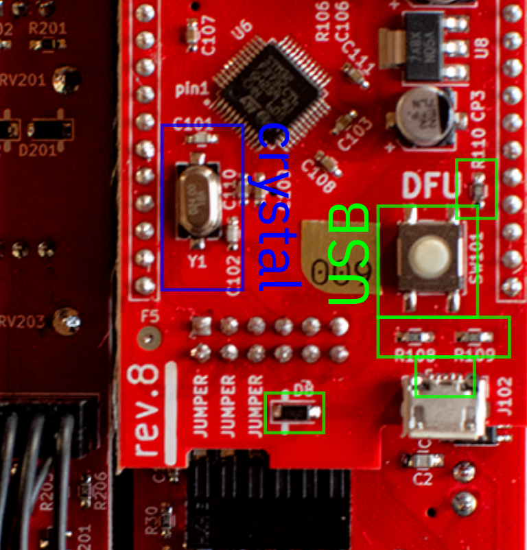
Make and place 17-pin headers.
Snap off two sections of the .1" single row header pins so you have 17 pins on each. Cut down a pair of 17-pin socket headers to match. Push the long end of the pins into the socket headers.
Seat the headers in the analog and digital board. It will make your life easier to solder the socket headers into the smaller digital board and the pin headers into the larger analog board.
Note that the SMT parts are facing up on both boards when you make the header sandwich. Take care when placing the headers unless you want desoldering practice.
Stack the two boards and solder the headers.
Take your time with this part to ensure proper alignment. Add light pressure so that the headers are flush with the PCB as you begin to solder. Solder the pins on the two opposite corners of the digital board and check that the headers are still aligned correctly.
Once you are satisfied with the alignment, secure the headers by soldering the rest of the pins, then flip and repeat with the other side. You can now separate the two boards.
Add the digital board power header.
Snap off a 10-pin chunk of the dual-row .1" headers, place it so the pins are sticking up from the component side of the board, and solder it in place, tacking a single pin down first to lock in alignment. It helps to prop up one side of the board to make sure that the header lies flush with the PCB.
This revision can only accommodate an un-shrouded header, but red stripe is down, and the power circuit is reverse protected.
Add the digital board expander header.
This belongs on the underside of the digital board, so the solder points will be on the same side as the SMT parts. It's good practice to put the expander cable on the header when soldering it in place to ensure the proper clearance.
As you can tell from the false start in the video, getting the alignment is a bit tricky, but you can prop up the digital board with the other boards to make it easier to get the first solder joint in place.
Attach the expander header.
Let's get the headers out of the way. Break away a 12-pin chunk of .1" dual-row pin headers and place it on the silkscreen indicator (the pins stick up from the component side of the board). Solder from the opposite side as shown.
As with all the other headers, figure out a way to get the alignment, tack a corner, and secure all the pins once your first solder joint locks in the alignment.
Phew, headers are done!
Insert the pots into the analog board.
Insert the pots into the side of the board with the silkscreen outlines. Note the placement of the 50K pot. When placing the pots, it helps to lead with the 3 pins and then push the lugs through.
Place the LEDs.
You might want to start with the cloudy bicolor LED so you don't mix it up with one of the clear white LEDs. For all 5 of the two-legged LEDs, in this corner of the universe the short lead goes to the square hole. You can let the LEDs sit in the holes against the PCB for now.
For the RGB LED, the longest lead goes next to the square hole. You might need to fiddle with this one a bit because the holes are close together, which gives you extra time to make sure that you have it oriented correctly.
Place the jacks.
The next step requires attaching the faceplate, so make sure that the faceplate and pot nuts are within reach before you start. Place the jacks while holding the board level with the other hand. The ground pins that stick out from the jacks should all be facing the same direction (towards the potentiometers).
Attach the faceplate.
Make sure all the pots are sitting flush and then ease the faceplate onto them. It should slide right down and onto the jacks with minimal fiddling. Once it is sitting flush on the pots and jacks, drop one or all of the pot washer/nuts on and secure them enough to hold the board in place.
This should make the assembly secure enough to set aside while you prepare to attach the expander.
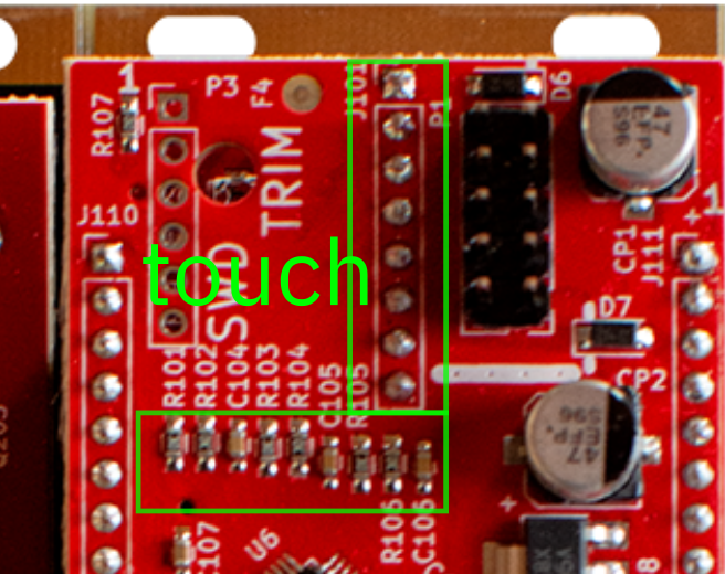
Place the expander parts.
First off, make sure that you are placing the parts on the side of the board opposite the components (just like the analog board).
Make sure the middle potentiometer is 50k as per the silkscreen.
The jacks have the same orientation as the analog board; ground lug towards the top of the board.
Take care with the orientation of the pushbutton; as shown on the silkscreen, the flatted side goes towards the bottom edge of the PCB.
Attach the expander to the faceplate
This should go down pretty much the same as when you attached the analog board to the faceplate. As before, secure the assembly with one or all of the pot nut/washers.
Add the rest of the nuts and washers
Now that the full assembly is secure, you can add the rest of the nuts and washers and tighten them up (no need to go overboard with the torque, that can pull the PCBs out of alignment).
A nut driver or socket is recommended, as pliers could mar your faceplate. Finger tightening might be a bit fidgety, but you should be able to get everything tight enough if you have to go that route.
Solder the delicate bits
Make sure the the PCBs are aligned and sitting flush against the components. Tightening the nuts can pull the expander board out of alignment.
The pushbutton needs to be pressed up flush against the PCB when it's soldered, so maybe start with that. You can use finesse and hold it up with your solder-feeding hand, or you can make your life easier and prop it up with something. Again, tack a pin and check alignment then secure the rest when you are happy.
The two-legged LEDs should be pushed through the holes in the faceplate as far as possible. The RGB LED gets pulled up so it is flush with the PCB.
TAKE YOUR TIME WITH THE RGB LED, IT'S THE HARDEST PART OF THE WHOLE THING.The hack here is to solder one pin, clip down the leads, then solder the rest to avoid bridges. That makes it comparable to soldering an IC. Go
Solder everything else
Now you can enjoy the zen of synth DIY and solder all of the remaining connections.
Reattach the analog board to the faceplate and insert the long header.
Insert the long 8 pin header through the analog board so that it is resting lightly in the socket header on the front panel. Attach the digital board to the analog board, seating the long pin headers before fully inserting. Keeping the base of the long pin header flush with the digital board, solder the two opposite pins on the header. Double check the alignment, then solder the rest. When disassembled, the long header stays attached to the digital board.
No Expander?
If you're not using the expander, make sure you place the 3 jumpers as shown here.
Expander?
Insert your expander cable paying attention to the white stripes present on the board and the white wires on the cable. Your Via will be extremely unhappy and likely suffer damage if you reverse this cable.
You're done with the hardware build!
Now, its time to program the microcontroller and calibrate the unit.